

In this short series of blogs, we have looked at noise and how it can disturb the operation of microcontroller-based systems. In this final blog, we will look at some of the “rules” we can use to minimize the impact of noise.
There are some golden rules we can use to minimize EMC in our design.
- Guard memory/clock traces from other signals.
- Consider filtering and/or buffering external connections.
- Always use high-frequency Vcc/Vss bypass capacitors close to every device.
- Always Vcc/Vss traces parallel and as close together as possible to minimize current loops.
- Try to use parallel signal/return traces on PCB, especially for fast signals or traces carrying substantial current.
- Consider the use of a multilayer layer board… with dedicated, unbroken Vss/Vcc planes.
- Don’t use a higher frequency than required, this is not only good for minimizing noise but power consumption as well.
Let’s look at some of these in a little more detail.
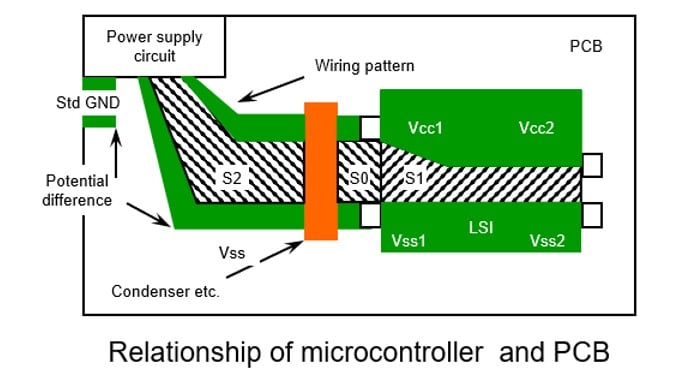
We should try to keep the area between the power supply lines as small as possible to minimize the potential antenna. We should also minimize the current flow to this antenna to keep any radiated noise to a minimum.
The system power supply is often one of the largest sources of internal noise in a system. Therefore, it is very important to design an effective power distribution system using bypass capacitors and EMI filters. We should keep the Antenna pattern area between the power traces on the PCB as small as possible so that the surrounding current loop area (S0, S1, S2) is reduced to a minimum. The most effective way to do this is to use parallel tracks for Vcc and Vss lines.
A bypass capacitor connected across the power supply lines to every IC will significantly reduce noise, we should try to keep these as close as possible to each device, typically, the most effective capacitor values are 0.01 µ F ~ 0.1 µF. In a particular noisy system, it may be worth combining different values of a capacitor to try to improve the noise performance.
Due to differences in the high-frequency characteristics of various types of bypass capacitors, choose the most suitable, lowest impedance capacitor according to the noise frequency range. For most Microcontrollers, ceramic and tantalum type capacitors are usually suitable. Use an electrolytic capacitor for filtering at the PCB power supply Input.
We should try to minimize the number of tracks between devices and keep the length of each as short as possible. Tracks between the MCU and other devices act like an antenna which causes noise. Consider the use of a serial bus, such as I2C or SPI, to talk to external devices rather than a full parallel bus. This minimizes noise and typically minimizes power consumption and PCB space as well. These are typically high-frequency connections, so be sure to keep the traces short.
Traces that carry high current in a design need special care, don’t place large current traces near the oscillator near other pins, such as the mode or reset pin, which could easily be interfered with by noise.
We’ve already spoken about the oscillator circuit in the previous blog, but this is a special area to take care of, especially if your design uses the low-power 32 kHz crystal for low-power operation. The most important points about the design of the circuit around the oscillator are to follow the oscillator circuit layout in the hardware manual, and to follow the circuit recommendations of your oscillator supplier, and to take advantage of their oscillator specification service if they offer this (especially for a 32 kHz oscillator design). Other key recommendations include not allowing other signal lines to cross the oscillator traces, as this causes crosstalk.
Keep signal and power supply tracks as far as possible from the oscillator as possible, and do not feed the ground between the pins of the MCU.
Other good layout practices for microcontroller systems include:
- Use Wide and Short Traces for Vcc/Vss wherever possible.
- Reducing the impedance of the power supply circuit will reduce inductive noise problems.
- Use Vss/Vcc planes where possible. At higher frequencies, typically > 4 MHz, the return current follows as closely to the signal path as possible. Therefore, plan signal returns paths carefully, especially for signals with high currents.
- Don’t break the ground plane, as this increases signal path impedance.
- Consider using current limiting resistors on I/O pins.
Renesas has used a wide range of design techniques inside our RA microcontrollers to minimize the issues caused by external noise. We typically use techniques such as the Separate CPU Bus (with memory) from a peripheral bus, which can minimize disturbance of the CPU operation, a distributed clock system, and a module stop function on every peripheral. We also use on-chip noise filtering on some of the more sensitive inputs, such as reset, oscillator inputs, etc., as well as optimizing the I/O buffers and the power supply design.
The integration of various components that otherwise would have to be external due to the advanced process technology that we use also helps to improve reliability removing the need for external circuitry such as oscillators and power management devices. The implementation of on-chip oscillators, POR / LVD (brownout systems), and watchdog timers on-chip can greatly reduce the areas where external noise can enter the chip.
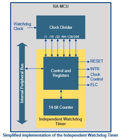
Software features on the microcontroller can be used to increase overall system immunity to noise effects. The correct use of the watchdog timers can recover applications from EMI-induced system crashes. Many of today’s RA microcontrollers have two watchdog timers, one clocked from the main clock system and the second clocked from a dedicated on-chip oscillator, this is the Independent Watchdog Timer (IWDT). The correct use of both watchdog timers allows the user to maintain an operating watchdog even in low-power mode, where traditional watchdogs may not be able to be used.
The application itself may be used to monitor its own progress and spot if any unforeseen operation occurs. Even with all these design features and techniques, removing noise before it can enter the chip and disturb its operation is always the most reliable way of maintaining safe operation.
I hope that this series of blogs has given some ideas and some food for thought, there is a lot more that we can say about noise in microcontroller systems, we have not considered areas such as the noise in different types of cabling, or the use of protection circuits such as Transils, Transorbs, Mosorbs, ... but I hope that you have found this short discussion about noise in Microcontroller systems useful. You can find more information about Renesas microcontrollers and information about their noise performance, as well as additional support documentation about noise issues, on our website.
Related Blogs
Reducing Noise Issues in Microcontroller Systems - Part 1
Reducing Noise Issues in Microcontroller Systems - Part 2
Reducing Noise Issues in Microcontroller Systems - Part 4